
How to install a Pyrofuse safely depends on three things: a trained high-voltage technician, the correct product datasheet, and the vehicle or equipment manufacturer’s service procedure. The basic process includes isolating all power sources, verifying zero voltage, inspecting the Pyrofuse, preparing the busbar surfaces, tightening the terminals to the specified torque, connecting the trigger circuit, checking joint resistance, and completing system diagnostics.
A Pyrofuse is both a pyrotechnic safety device and a high-current electrical component. Incorrect handling can cause unintended activation, poor electrical contact, excessive heating, diagnostic faults, or failure to disconnect the battery during an emergency.
The procedure below explains the main engineering principles. Actual mounting torque, trigger current, connector sequence, resistance limits, and commissioning steps must come from the documentation for the exact Pyrofuse and system.
What Is a Pyrofuse?
A Pyrofuse is a fast battery disconnect device used in electric vehicles, hybrid vehicles, energy storage systems, charging equipment, and other high-voltage DC applications. When the control unit detects a severe crash, short circuit, or other hazardous event, an electrical trigger activates a small pyrotechnic charge. The resulting mechanical action cuts or separates the high-current conductor.
Unlike a conventional fuse, a Pyrofuse can be triggered by a control signal before fault current reaches the melting threshold of a passive fuse. See what a Pyrofuse is and the difference between a fuse and a Pyrofuse for more background.
Before Installing a Pyrofuse
| Check | What to confirm |
|---|---|
| Part identification | Part number, voltage rating, continuous current, breaking capacity, trigger specification, and physical dimensions match the application. |
| System state | The high-voltage system is shut down, isolated, discharged, and verified at zero voltage. |
| Mounting interface | Busbars are clean, flat, aligned, and free of oxidation or damage. |
| Fasteners | Correct bolts, washers, thread engagement, and product-specific torque values are available. |
| Trigger circuit | The connector, polarity where applicable, interlock, diagnostic circuit, and firing-control procedure are correct. |
| Replacement cause | If replacing a deployed unit, the event that caused activation has been diagnosed and corrected. |
Tools and Safety Equipment
- Appropriate electrical PPE for the system voltage and local rules
- Insulated tools and a calibrated torque wrench
- Approved voltage detector and proving unit
- Lockout/tagout equipment and warning signs
- Clean lint-free cloths and approved contact-cleaning materials
- Product-specific fixtures, gauges, or joint-resistance test equipment
- Manufacturer-approved diagnostic equipment
How to Install a Pyrofuse Step by Step
1. Verify the Pyrofuse and System Requirements
Confirm the exact Pyrofuse part number before opening the high-voltage system. Compare the voltage rating, current rating, interrupting performance, trigger characteristics, terminal geometry, mounting orientation, and environmental limits with the engineering specification.
Do not substitute a visually similar model. A different trigger energy, conductor design, internal resistance, or breaking capacity can change how the protection system responds.
2. Make the Vehicle or Equipment Electrically Safe
Park or secure the equipment, switch off all power sources, remove service disconnects where specified, isolate auxiliary supplies, and apply lockout/tagout. Wait for the stated capacitor discharge time, then prove the voltage detector, test the required points, and prove the detector again.
Follow the OEM sequence exactly. As one practical reference, Tesla’s service documentation shows the type of structured isolation and verification process used for high-voltage repairs: Tesla Model Y high-voltage disable procedure.
3. Prevent Unintended Pyrotechnic Activation
Keep the trigger connector disconnected until the mechanical and high-current electrical work is complete, unless the manufacturer’s procedure specifies another sequence. Control static electricity, keep ignition sources away, and do not probe the initiator with unapproved instruments.
4. Inspect the New Pyrofuse
Check the housing, terminals, connector, seals, labels, and shipping protection. Do not install a Pyrofuse that has been dropped. Internal pyrotechnic or mechanical damage may not be visible from the outside. Always follow the handling, storage, inspection, and mounting requirements specified for the selected product.
5. Prepare the Mounting Location and Busbars
Remove contamination, oxidation, burrs, and loose particles using approved methods. Confirm that the mating surfaces are flat and the busbars meet the drawing tolerances. The terminals should meet naturally without using the Pyrofuse body or fasteners to force misaligned conductors together.
6. Position and Mechanically Secure the Pyrofuse
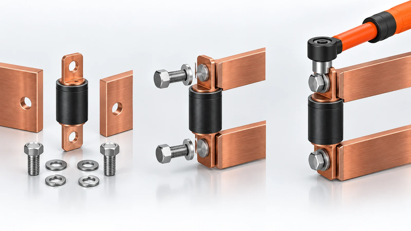
Place the Pyrofuse in the specified orientation and install any supports before tightening the high-current terminals. Start all fasteners by hand, then tighten them in the required sequence with a calibrated torque wrench.
There is no universal Pyrofuse torque value. Use the product drawing and system work instruction. For example, the Chauron SPF-2L Pyrofuse specifies 14 N·m for its terminal connection, but that value must not be applied to another model unless its documentation gives the same requirement.
7. Connect the Trigger and Diagnostic Circuit
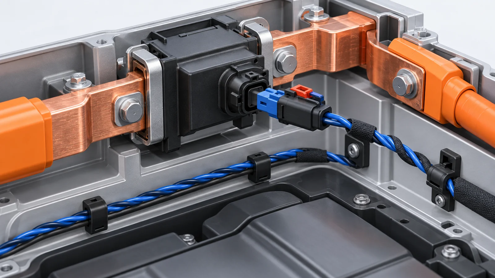
After the mechanical installation is complete, inspect the low-voltage connector and harness. Confirm connector keying, pin condition, harness routing, retention, interlock continuity, and any required shielding. Connect the trigger circuit only at the point defined by the manufacturer’s procedure.
Never apply power directly to the initiator as a functional test. Use the approved diagnostic method to check circuit status without risking deployment. Read more about active and passive Pyrofuse triggering.
8. Verify the Electrical Joint
Perform a visual and mechanical inspection, then measure joint resistance or voltage drop if required. A poor joint can carry normal current initially but create heat, oxidation, and voltage loss over time. Record the torque and resistance values when the quality plan requires traceability.
9. Restore Power and Complete Diagnostics
Refit covers and barriers, remove tools and loose items, reconnect the service disconnects in the prescribed order, and restore the auxiliary and high-voltage supplies. Run the approved diagnostic routine and confirm that the Pyrofuse circuit, high-voltage interlock loop, insulation monitoring, and related controllers show no faults.
Do not clear a recurring fault without finding its cause. Verify the system remains stable during the prescribed functional checks.
Installing a Pyrofuse in a New System vs. Replacing One
| New system integration | Replacement after deployment |
|---|---|
| Validate electrical ratings, coordination, trigger logic, busbar stress, thermal performance, and packaging. | Identify why the original unit deployed and inspect surrounding conductors, modules, and control circuits. |
| Define torque, resistance, connector, environmental, and end-of-line test requirements. | Follow the OEM repair sequence and replace any single-use fasteners or damaged harness components. |
| Complete validation testing before production release. | Complete diagnostics and confirm the initiating event will not recur. |
Common Pyrofuse Installation Mistakes
Using a Generic Torque Value
Too little torque increases contact resistance. Too much torque can damage threads, terminals, insulation, or the housing. Always use the exact product specification.
Connecting the Trigger Circuit Too Early
An early connection increases exposure to unintended activation while tools and hands are still near the device.
Failing to Verify Zero Voltage
Opening a service disconnect does not prove the circuit is safe. Stored energy and alternate feeds must be considered.
Reusing a Deployed Pyrofuse
A deployed Pyrofuse is a single-use safety component. It cannot be reset and should be replaced with the specified part.
Installing a Dropped or Damaged Device
Hidden damage can affect the pyrotechnic initiator, conductor, seals, or mechanical cutting mechanism.
Measuring the Initiator with an Unapproved Meter
Some meters can inject test current. Use only methods explicitly approved for the trigger circuit.
Ignoring Busbar Alignment
Forcing the terminals into position can place permanent mechanical stress on the Pyrofuse and create an uneven contact interface.
Replacing the Device Without Diagnosing the Trigger Event
A crash signal, isolation fault, short circuit, damaged controller, or wiring problem may still be present after the old unit is removed.
Frequently Asked Questions
Can I install a Pyrofuse myself?
Pyrofuse installation should be performed by personnel trained and authorized for the relevant high-voltage and pyrotechnic system. It is not a general DIY repair.
Does the battery need to be disconnected?
Yes. All relevant energy sources must be isolated, stored energy discharged, and zero voltage verified according to the OEM or system procedure.
What torque should be used for a Pyrofuse?
Use the value specified for the exact model and terminal hardware. There is no safe universal torque value.
Should the trigger connector be connected first?
Usually the mechanical and high-current connections are completed first, but the exact sequence must follow the manufacturer’s instructions.
Can a multimeter test a Pyrofuse?
Do not place a standard meter across a pyrotechnic initiator unless the manufacturer explicitly approves the test method. An inappropriate test current could create a hazard.
Can a deployed Pyrofuse be reset?
No. A deployed Pyrofuse is replaced as a complete single-use safety component.
Why measure joint resistance after installation?
Low and stable joint resistance helps confirm correct surface preparation, alignment, and clamping. It also reduces the risk of localized heating.
Does a Pyrofuse replace the main battery fuse?
System architecture varies. Some designs use both a Pyrofuse and a passive fuse because they protect against different fault conditions. See Pyrofuse vs. traditional T-link fuse.
Conclusion
Safe Pyrofuse installation depends on system isolation, correct part selection, careful handling, clean and aligned busbar joints, product-specific torque, controlled trigger-circuit connection, resistance verification, and complete diagnostics. Treat every value and sequence in this guide as an engineering framework, then apply the requirements for the exact device and vehicle or equipment.
For help selecting or integrating a Pyrofuse for an EV, energy-storage system, charging system, or high-voltage DC application, browse the Chauron Pyrofuse range or contact Chauron with your system voltage, continuous current, prospective fault current, circuit inductance, busbar dimensions, operating temperature, and trigger requirements.