
Fuse, circuit breaker and protection symbols identify where an electrical circuit detects a fault, interrupts current, isolates equipment or provides personnel protection. The exact drawing can vary between IEC, ANSI/IEEE, automotive and company-specific standards, so each symbol must be read with its reference designation, ratings, legend and surrounding circuit.
Fuse, Circuit Breaker and Protection Symbols at a Glance
The table below summarizes common functions. It describes typical appearances rather than one universal drawing, because approved variants differ among standards and industries.
| Device or function | Typical schematic appearance | Main purpose | Common drawing clues |
|---|---|---|---|
| Fuse | Small rectangle inserted in the conductor; some ANSI drawings use a curved element | Opens permanently when overcurrent melts the fuse element | F or FU tag; current, voltage, class or speed may appear nearby |
| Thermal fuse | Fuse modified to show temperature-dependent operation | Opens at a specified temperature | Temperature value or thermal notation |
| Fuse switch / fuse disconnector | Fuse combined with switching or isolating contacts | Provides fused protection with switching or isolation | Combined fuse, switch and disconnector functions |
| Circuit breaker | Switching contacts with an automatic trip function | Opens during a defined fault and can normally be reset | CB, QF or other device tag |
| RCD or RCBO | Switching device with differential-current sensing | Trips when outgoing and returning current differ | Sensing core, test circuit or residual-current rating |
| Overload relay | Current-sensitive relay function | Protects motors from sustained overload | Linked to a contactor control circuit |
| Protective relay | Relay block identified by a protection function | Detects abnormal conditions and commands a trip | Function code, CT/VT inputs and trip output |
| Surge protective device | Protection element connected from line to line or earth | Limits transient overvoltage | Usually connected in parallel |
| Disconnector | Open switching contact emphasizing isolation | Creates a defined isolation point | May not have fault-interrupting capability |
| Contactor | Power contacts linked to an operating coil | Performs frequent normal switching | Coil and contacts can be cross-referenced |
| Protective earth | Standard earth symbol for protective bonding | Provides a safety path for fault current | Do not confuse with functional earth or signal reference |
Symbols communicate a device’s function; they do not by themselves reveal current rating, voltage rating, breaking capacity, time-current characteristic, package or AC/DC suitability.
What Does a Fuse Symbol Mean?
A fuse symbol marks a one-time overcurrent protection device connected in series with the circuit it protects. Current passes through a calibrated element in normal operation. When current and time produce enough heat, the element melts and creates an open circuit.
The same general symbol may represent a cartridge fuse, automotive blade fuse, semiconductor fuse, bolt-down battery fuse or high-voltage DC fuse. The bill of materials and device schedule identify the actual part. When reading a fuse symbol, check the reference designation, rated current and voltage, AC/DC application, time-current characteristic, breaking capacity, utilization category and any associated holder or disconnect function.
Physical appearance alone is not enough when selecting a replacement. Our automotive fuse types guide shows how blade, cartridge, bolt-down, EV and pyrotechnic devices can have very different electrical functions even when all are called fuses.
What Does a Circuit Breaker Symbol Mean?
A circuit breaker symbol represents a device that can make, carry and interrupt current, including automatic interruption under specified fault conditions. Unlike a conventional fuse, a circuit breaker normally opens contacts through a trip mechanism and can be reset after the fault is cleared.
The basic symbol may be supplemented by thermal, magnetic, electronic, undervoltage, shunt-trip or residual-current functions. A three-pole breaker is often drawn as three mechanically linked contacts. In a single-line diagram, one symbol may represent all poles, with the pole count stated nearby.
Check the schedule or notes for rated current and frame size, rated operational voltage, number of poles, trip curve or settings, short-circuit breaking capacity, AC/DC rating, isolation suitability and auxiliary contacts. A breaker symbol alone does not prove the device is suitable as an isolator or can interrupt the available DC fault current.
Fuse Symbol vs. Circuit Breaker Symbol
A fuse and circuit breaker can both open a circuit during overcurrent, but their symbols describe different mechanisms and maintenance expectations.
| Comparison | Fuse | Circuit breaker |
|---|---|---|
| Operating principle | Fuse element melts | Contacts open through a trip mechanism |
| Reusability | Single-use | Normally resettable |
| External control | Usually none | May support shunt trip, undervoltage trip or remote control |
| Current limitation | Can be highly effective with the correct current-limiting fuse | Depends on breaker design and operating speed |
| After operation | Replace the fuse and diagnose the fault | Diagnose, inspect as required and reset or service the breaker |
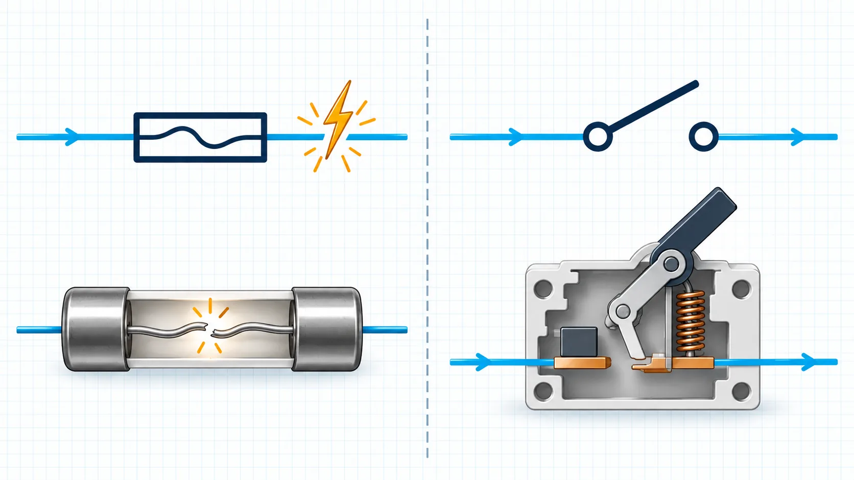
In high-energy DC systems, a fuse may limit peak current and energy very quickly, while a breaker can provide controllable or resettable isolation. Engineers coordinate the devices according to the fault-current profile and the withstand capability of cables, contactors, busbars and power semiconductors.
IEC vs. ANSI/IEEE Electrical Symbols
IEC and ANSI/IEEE drawings can use different graphical forms for the same general function. Older drawings, regional practices, CAD libraries and company standards introduce additional variants.
The international reference is the IEC 60617 graphical symbols database, which includes general fuse symbols and related protection functions. North American drawings may instead follow IEEE or ANSI conventions, while automotive diagrams often use OEM-specific symbol libraries.
| Drawing issue | IEC-oriented practice | ANSI/IEEE-oriented practice |
|---|---|---|
| Fuse | Commonly represented by a rectangular symbol in the conductor | Curved, S-shaped or other established variants may appear |
| Circuit breaker | Switching contacts are combined with the appropriate breaker function | A breaker contact or device symbol may be used with standard identification |
| Protective functions | Functional qualifying symbols can be combined with the main device | Device numbers and relay-function notation are often prominent |
Never identify a device from shape alone when the drawing standard is unknown. Start with the title block, legend and drawing notes. If different symbol systems are mixed in one project, the legend governs that document.
Common Electrical Protection Symbols
Thermal Fuse Symbol
A thermal fuse responds primarily to temperature. It is a single-use device often installed close to windings, heating elements, transformers or battery cells. Do not confuse it with a resettable thermostat or thermal circuit breaker.
Fuse Switch and Fuse Disconnector Symbols
A fuse switch combines switching and fuse functions. A fuse disconnector combines fuse protection with isolation. Do not assume every fuse holder is a load-break switch, or that a switch-fuse provides verified isolation unless the specification says so.
Residual-Current Protection Symbol
Residual-current protection detects an imbalance between conductors. The drawing can show a sensing core around conductors, a test circuit and a trip connection. Names such as RCD, RCCB, RCBO and GFCI depend on region and function, so check the complete label.
Overload Relay Symbol
An overload relay protects a motor against sustained overcurrent and normally commands a contactor to open rather than interrupting the power circuit itself. Motor circuits often use a fuse or breaker for short circuits and a separate overload relay for thermal overload.
Surge Protection Symbol
A surge protective device limits transient overvoltage. It is generally connected in parallel between conductors or from a conductor to earth, unlike a series fuse. The symbol does not specify voltage protection level, discharge current or energy capability.
Protective Relay Symbol
A protective relay measures current, voltage, frequency, impedance, differential current or another quantity, then issues a trip command. Follow cross-references before assuming that the relay itself interrupts the main current.
Circuit Breaker, Disconnector and Contactor Symbols
| Device | Normal role | Automatic fault operation | Frequent switching | Isolation capability |
|---|---|---|---|---|
| Circuit breaker | Protect and switch a circuit | Yes | Product-dependent | Product-dependent |
| Disconnector | Isolate equipment | Usually no | Usually limited | Primary function |
| Contactor | Electrically control a load | Only when commanded by protection | Yes | Usually not a substitute for a safety isolator |
Mechanical linkage, trip units, coils, auxiliary contacts and device tags help distinguish them. The drawing legend should define how combined devices are represented.
Protection Symbols in EV and High-Voltage DC Systems
An EV or battery-energy system rarely depends on one protection component. A single-line diagram may show a service disconnect, high-voltage fuse, positive and negative contactors, pre-charge contactor and resistor, current sensor, insulation monitoring device, Pyrofuse and battery management system.
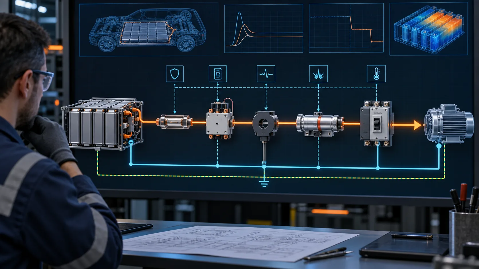
- Conventional EV fuse: passive overcurrent and short-circuit protection
- Main contactors: normal connection and disconnection of the traction circuit
- Service disconnect: manual maintenance isolation
- Current sensor: measurement for control and fault detection
- Insulation monitor: detection of isolation faults between the high-voltage system and chassis
- Pyrofuse: fast, irreversible battery isolation after an electronic trigger
A Pyrofuse may be drawn as a special fuse, triggered disconnect or project-specific functional block. It should not automatically be interpreted as a conventional thermal fuse. See what a Pyrofuse is and the difference between a fuse and a Pyrofuse for the operating distinction.
Many EV architectures use both technologies. The passive fuse responds to fault current, while the Pyrofuse responds to a command from the BMS, airbag controller or other safety system. The Pyrofuse vs. traditional T-link fuse comparison explains why these functions can complement each other.
How to Read Protection Symbols on an Electrical Drawing
- Identify the drawing type. Determine whether it is a schematic, wiring diagram, single-line diagram, functional diagram or physical layout.
- Read the title block. Check the applicable standard, project, revision and document status.
- Find the legend. The project legend takes priority when a symbol has several accepted variants.
- Read the reference designation. Tags such as F1, CB2, QF3 or K1 connect the symbol to the bill of materials and device schedule.
- Trace the current path. Series devices usually interrupt or switch current; parallel devices often clamp voltage or measure a condition.
- Follow dashed and mechanical links. These may connect poles, auxiliary contacts, trip units, sensors or remote actuators.
- Check ratings and notes. Confirm voltage, current, breaking capacity, trip settings and AC/DC suitability.
- Verify the actual component. Before installation or replacement, use the part number and approved documentation rather than relying on the symbol.
For pyrotechnic protection, the trigger and diagnostic circuit matters as much as the high-current path. Our Pyrofuse installation guide explains why both need separate checks.
Common Mistakes When Reading Protection Symbols
Assuming One Symbol Has One Universal Shape
IEC, ANSI/IEEE, automotive and company libraries use different variants. The legend and drawing standard resolve the meaning.
Treating a Fuse Symbol as a Complete Specification
A symbol does not define current rating, voltage, breaking capacity, speed, I²t, dimensions or mounting method.
Confusing a Circuit Breaker with an Isolator
Both can show open contacts, but their rated functions differ. A device must be specifically suitable for isolation if that function is required.
Confusing a Contactor with a Circuit Breaker
A contactor performs commanded switching. It normally depends on a separate protective device or controller to detect a fault.
Ignoring AC and DC Ratings
The same general symbol can appear in AC and DC diagrams. High-voltage DC interruption is demanding because the arc has no natural current zero. Always verify the device’s DC rating and tested breaking capacity.
Frequently Asked Questions
What is the electrical symbol for a fuse?
The IEC-oriented fuse symbol is commonly shown as a small rectangle inserted in the conductor. ANSI/IEEE and legacy drawings may use other forms, including curved or S-shaped elements. Check the drawing legend before interpreting an unfamiliar version.
What is the difference between a fuse symbol and a circuit breaker symbol?
A fuse symbol represents a sacrificial element that melts and must be replaced. A circuit breaker symbol represents switching contacts with an automatic trip function and is normally resettable.
Is a fuse symbol different for AC and DC?
The general fuse function may use the same symbol. AC or DC suitability comes from the circuit context, ratings, notes and product specification.
What do F, FU, CB and QF mean on a schematic?
They are commonly used reference designations for fuses or circuit breakers, but conventions vary among standards and companies. Treat the drawing legend and equipment schedule as the controlling source.
Does an open-switch symbol always mean a circuit breaker?
No. It may represent a manual switch, disconnector, contactor contact or circuit breaker. Look for the trip function, coil, mechanical linkage and reference designation.
What symbol is used for a Pyrofuse?
There is no single representation used on every EV drawing. A project may use a qualified fuse symbol, a triggered disconnect symbol or a labeled functional block. The trigger circuit and component designation normally confirm the device.
Is an RCD the same as a circuit breaker?
An RCD detects residual current. Some products provide only residual-current protection, while an RCBO combines residual-current and overcurrent protection. Read the full device designation rather than relying only on the switching contacts.
Conclusion
Fuse, circuit breaker and protection symbols provide a compact language for electrical drawings. Correct interpretation requires more than memorizing shapes: identify the drawing standard, consult the legend, trace the current path, follow control links and verify device ratings in the schedule or datasheet.
This is particularly important in EV, energy-storage and other high-voltage DC systems, where a fuse, contactor, circuit breaker, service disconnect and Pyrofuse may perform complementary functions. If you are designing a protection architecture, Chauron can review your system voltage, continuous current, prospective fault current, load profile, circuit inductance and required disconnection strategy to help identify a suitable fuse or Pyrofuse solution.