
A photovoltaic fuse is an overcurrent protection device selected for the DC circuits of a solar power system. A suitable fuse must interrupt the faults that its circuit can produce while carrying normal generation current. For procurement, the specification needs to cover the fuse-link, its holder and the installation conditions together.
A purchase description such as “solar fuse, 20 A” leaves important questions unanswered. Which circuit will it protect? What is the maximum DC voltage? Which holder is approved? Those details determine whether the quoted part can be accepted.
I. What makes a fuse suitable for photovoltaic service?
Solar arrays have distinctive fault conditions. Healthy parallel strings may feed reverse current into a damaged string, while some faults produce relatively modest overcurrent. The fuse must clear the relevant fault without relying on the natural current-zero crossings found in AC circuits.
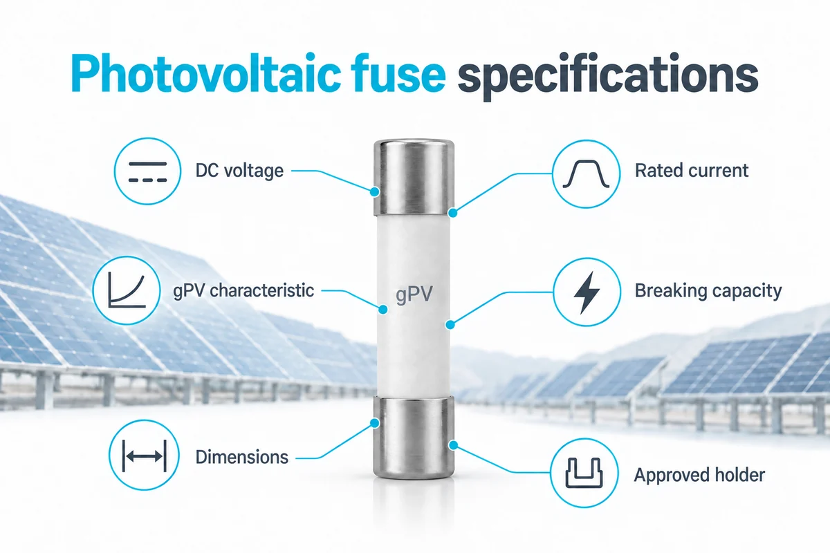
The gPV designation identifies a full-range photovoltaic fuse characteristic. It does not establish the rating for your installation or guarantee instantaneous clearing. The published scope of IEC 60269-6 covers fuse-links for protecting PV strings and arrays in circuits up to 1,500 V DC. Confirm the required standard edition and approvals against the project specification.
PV fuse, solar fuse and photovoltaic fuse commonly describe the same application. The wording on a sales page is not evidence of qualification. The exact part number and supporting documents matter. For background on string faults and sizing, see our PV fuse protection guide.
II. Photovoltaic fuse specifications to check before ordering
Ask for a model-specific datasheet and dimensional drawing. A product-family brochure may show several voltage ratings, mounting options and operating characteristics that do not apply to every item in the range.
| Specification | Evidence to request | Acceptance question |
|---|---|---|
| DC voltage rating | Rated voltage for the exact fuse and holder | Does the assembly cover the maximum calculated circuit voltage? |
| Rated current | Current rating and applicable correction guidance | Can it carry the design current without exceeding protection limits? |
| gPV characteristic | Application designation and relevant conformity documents | Is photovoltaic protection documented? |
| Breaking capacity | Interrupting rating with voltage and test conditions | Does it cover the prospective fault duty? |
| Time-current performance | Curves for the selected rating | Will the required faults clear before protected equipment is damaged? |
| Mechanical interface | Dimensions, terminal format and holder compatibility | Is the specified combination suitable electrically and mechanically? |
The distinctions between DC fuse types are useful when a project includes an array, inverter and battery system. Similar voltage markings do not make devices intended for different protection duties interchangeable.
III. Match the electrical rating to the circuit
Maximum voltage and current are separate checks
For a PV string, establish maximum open-circuit voltage using the module data, series module count and the required temperature correction. The inverter’s normal operating voltage is not a substitute for that maximum. A 1,000 V DC device cannot be accepted where the calculated voltage exceeds its rating.
Current selection starts with the module data and the design method required for the installation. Account for the applicable irradiance, bifacial contribution and temperature conditions. Avoid copying a fixed current multiplier from another project without checking its assumptions.
The module’s maximum series-fuse rating is a protection limit, not an instruction to fit that rating in every string. It should not be treated as an interchangeable measure of continuous reverse-current withstand. Check the module instructions and cable protection requirements alongside the fuse data.
Review low-current faults as well as maximum interruption duty
A high breaking-capacity value answers only part of the protection question. Establish whether the fuse will clear the lower fault currents available in the circuit within the required time. Check which curves describe pre-arcing and which describe total clearing; they represent different stages of operation.
String fuses and combined-output fuses may protect different conductors and carry very different currents. Review their coordination as part of the system design. Choosing the same utilization category throughout does not by itself establish selective operation.
IV. Check the photovoltaic fuse and holder together
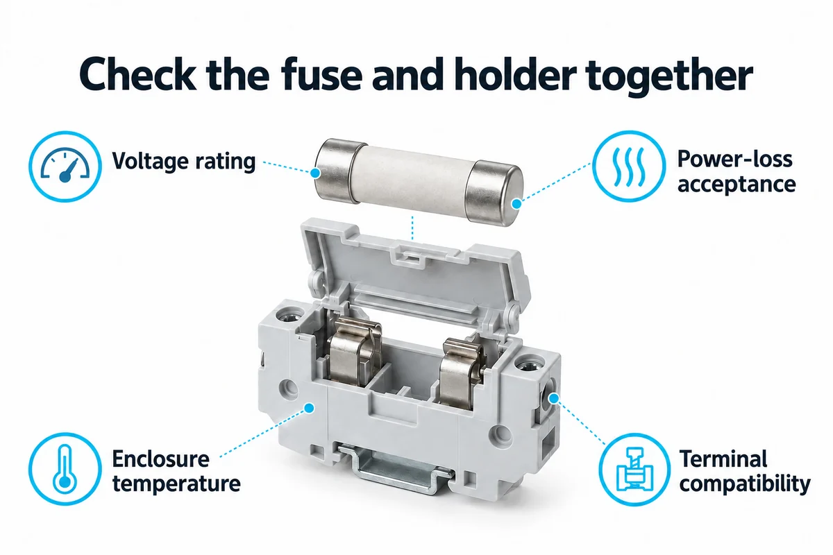
A fuse that fits can still be unsuitable for its holder. Check the holder’s DC voltage, permissible fuse power loss, current rating and installation restrictions. The holder documentation may require current reductions for elevated ambient temperature or closely grouped poles.
Use the temperature inside the enclosure, including heat from adjacent equipment, when applying the relevant guidance. An outdoor air-temperature figure may understate the conditions around a fuse inside a sun-exposed combiner box. Confirm how the manufacturer’s temperature and grouping corrections should be combined.
Cylindrical formats, in-line assemblies and NH or bolted fuse-links have different mounting requirements. Check the full drawing and approved pairing rather than assuming that a familiar diameter or a higher voltage rating guarantees compatibility. For outdoor equipment, verify environmental protection at assembly level.
Terminal conductor range, tightening requirements and contact condition also deserve a place in the acceptance record. A damaged contact or poor connection can create local heating even when load current is within the expected range. Servicing and installation must follow the equipment instructions.
V. Separate PV protection from battery disconnection
A solar-storage installation can contain several protection duties. The array circuit, battery branch and power-conversion equipment should each have a defined fault assessment. Whether the battery can feed a particular PV-side fault depends on the converter topology and isolation arrangement.
Battery fuses must be evaluated for battery-source fault current, operating cycles and the protected circuit. A photovoltaic fuse should not be substituted solely because its current and voltage labels match.
Where the system requires a commanded battery disconnect, a pyrofuse is a separate device to evaluate. Its trigger interface and interruption capability need application-specific assessment. It is not a drop-in replacement for a gPV string fuse.
VI. Prepare a photovoltaic fuse procurement checklist
Send enough information for suppliers to quote the same duty. Otherwise, prices may reflect different holders, terminal arrangements or qualification levels.
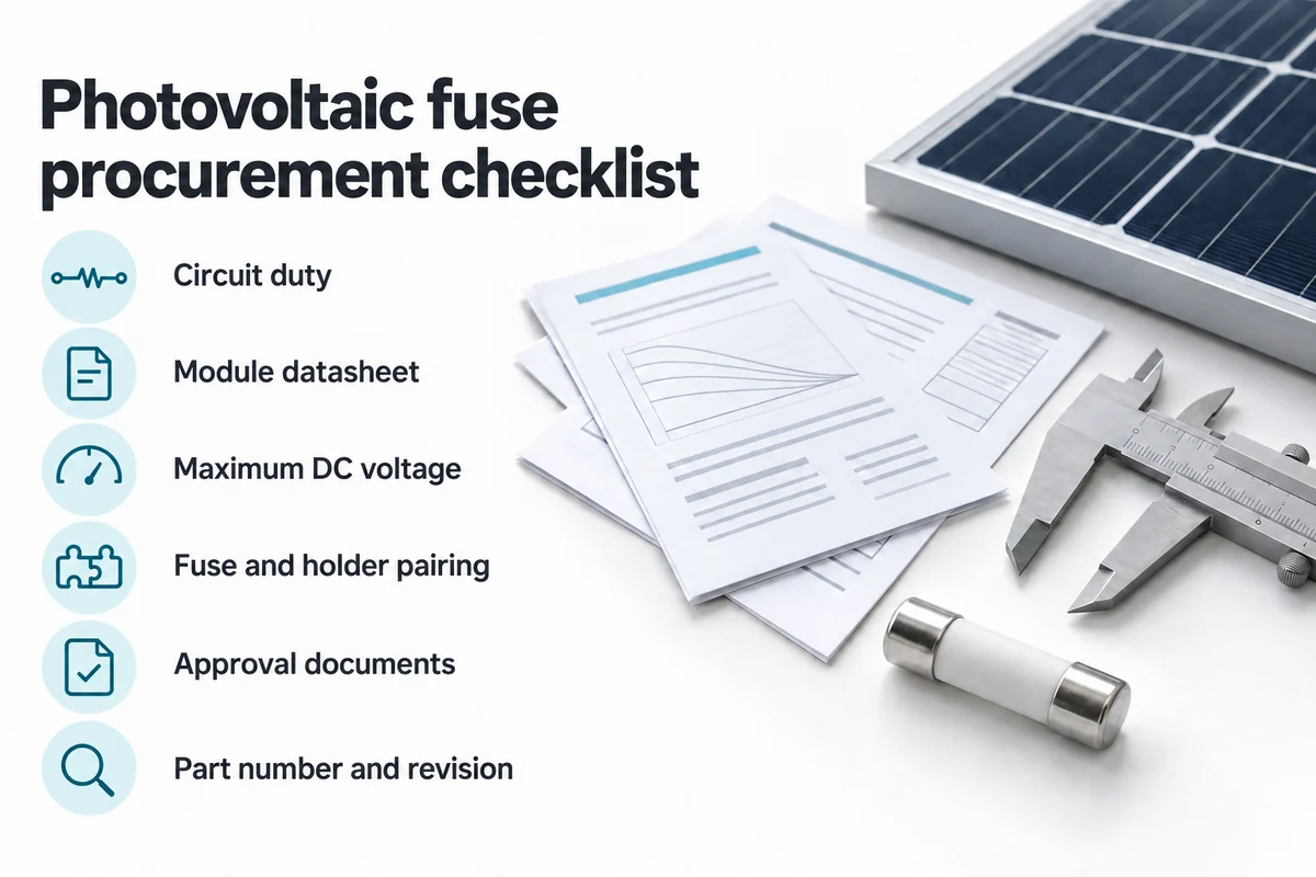
- Identify the protected circuit: string, combiner input, combined output or another DC branch.
- Provide the module datasheet, series and parallel arrangement, and design temperature range.
- State maximum DC voltage, design current, fault-current range and applicable protection limits.
- Include the holder part number, enclosure conditions, cable details and available mounting space.
- Specify required approvals, document revisions, quantity, packaging and replacement-part requirements.
Request confirmation of the exact fuse-link and holder combination in the quotation. Keep the accepted datasheet, drawing and qualification evidence with the bill of materials. If an approval document covers a family, confirm that the proposed part and rating are included.
A lower unit price may exclude the holder, indication accessory or documentation needed for acceptance. Compare like-for-like scope before approving a substitute. Delivery and minimum order quantity are commercial questions; they do not resolve a missing technical requirement.
VII. Control substitutions and replacement parts
Record the manufacturer, complete part number and accepted revision. Reopen the technical review when the module model, string arrangement, holder or enclosure changes. A fuse accepted for the original design may no longer meet the revised conditions.
For a proposed substitute, compare the operating curves, DC interruption data, dimensions, power loss, holder pairing and approval coverage. Matching the ampere rating and cartridge size is insufficient. Incoming inspection should check identification and documentation against the approved order.
After a fuse has operated, qualified personnel should investigate the cause before replacement. Increasing the rating to prevent another operation can compromise protection. Illuminated PV modules can continue producing voltage after a fuse opens; follow the equipment’s isolation procedure, and never use an ordinary fuse holder as a load-break switch.
VIII. Frequently asked questions
Is a photovoltaic fuse different from a solar fuse?
The terms usually refer to the same application. Neither name alone proves suitability. Check the exact product’s photovoltaic characteristic, DC voltage, operating curve and required approvals. A label describing a fuse as “solar compatible” is not a substitute for the documentation needed to accept it.
Can I replace a 1,000 V fuse with a 1,500 V fuse?
A higher voltage rating may meet the voltage requirement, but the replacement still needs the correct current rating, operating characteristic and approved holder combination. Dimensions and power loss can differ. Obtain approval for the complete substitution before changing the bill of materials or a field-installed component.
Does a 20 A fuse open as soon as current reaches 20 A?
No. Rated current is not an instantaneous trip threshold. Operating time depends on the current, fuse characteristic and conditions. Use the manufacturer’s time-current information to assess a specific fault. The 20 A marking alone does not tell you how quickly the fuse will interrupt that fault.
Are all gPV fuses interchangeable?
No. The utilization category does not make voltage ratings, dimensions, power losses or time-current behavior identical. Compare the exact parts and the holder requirements. Qualification for one assembly or installation should not be assumed to apply to a different combination, even when both fuse-links carry the gPV designation.
Can a PV fuse protect against every ground fault or arc fault?
No. A fault must produce enough current for the fuse to operate within the necessary time. Some ground-fault and series-arcing conditions require separate detection and protection. The system design must address those hazards; selecting a gPV fuse does not replace the other protective functions required for the installation.
What documents should accompany a photovoltaic fuse quotation?
Request a model-specific datasheet, dimensional drawing, relevant operating curves, holder compatibility information and the required conformity or approval evidence. Ask for the document revisions and complete ordering code. The supplier should identify any missing project data or conditions that still require engineering confirmation before the part is accepted.
IX. Discuss your project with Chauron
Send Chauron the circuit diagram, module data, voltage and current requirements, holder details and approval requirements with your fuse selection inquiry. Identify which circuits need gPV qualification and request model-specific supporting documents before approving a proposed device.