
An ESS fuse protects a defined battery or DC distribution path by interrupting overcurrent within its specified operating range. In a battery energy storage system, the right fuse depends on its position: a rack output, shared DC bus and power conversion system (PCS) input face different current profiles and fault sources. Select it from the circuit duty, then verify the chosen model’s clearing performance.
Storage projects often start with a voltage class and an ampere rating. Those figures narrow the catalog, but they do not show whether a fuse can clear the smallest fault that matters, survive normal cycling or coordinate with the rest of the system. The protection boundary comes first.
Where does an ESS fuse protect the system?
Draw the battery strings, rack outputs, common DC bus and PCS connection. At each proposed fuse position, mark the equipment and cable it is meant to protect. Then consider current from every connected source. A fault on one rack may receive contribution from other racks through the shared bus.
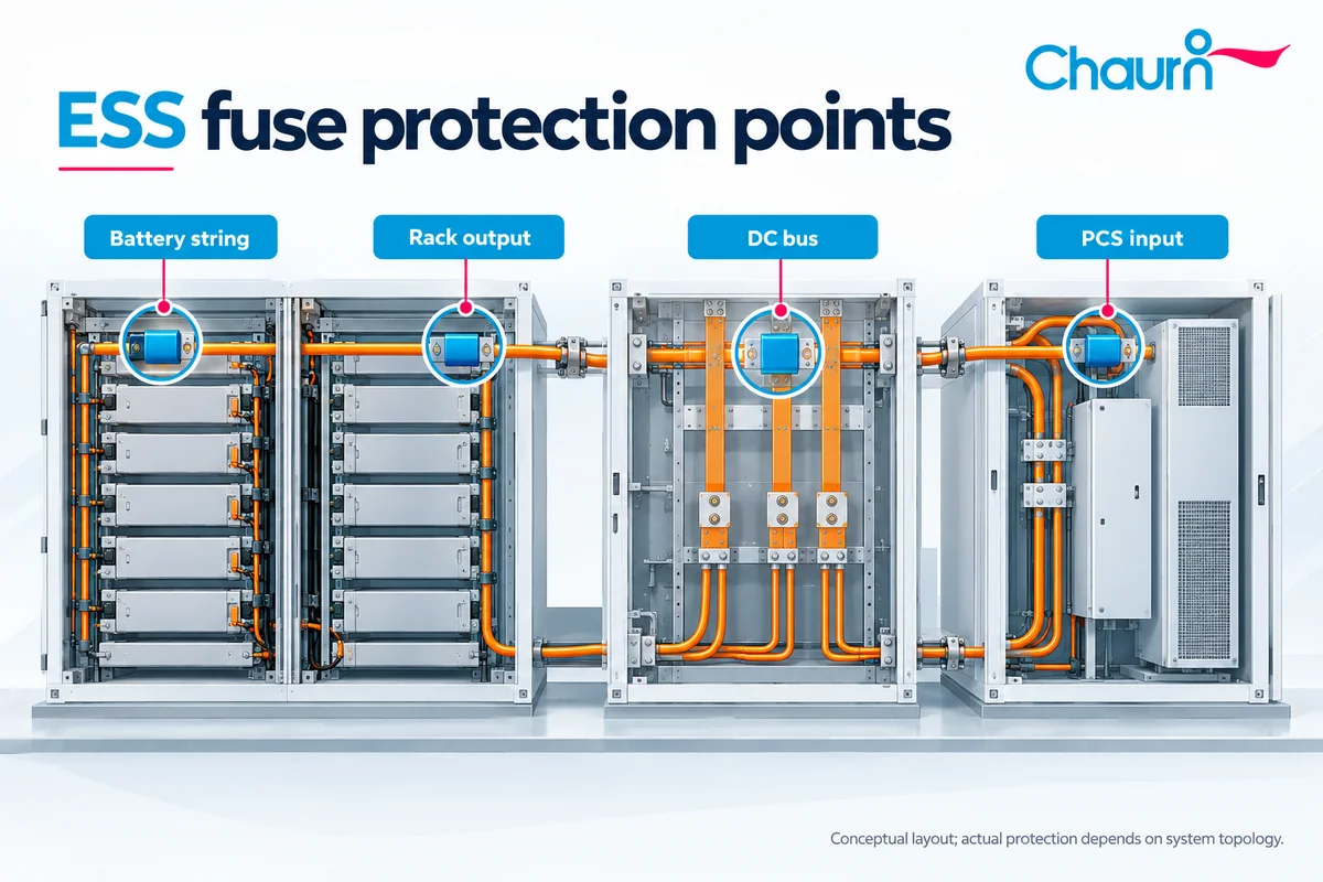
| Position | Protection question | Data the designer needs |
|---|---|---|
| Battery string or module connection | Can a fault in this branch be isolated before connected conductors exceed their limits? | Cell or module fault contribution, conductor withstand and the applicable fuse’s minimum clearing range. |
| Rack output | Can the affected rack separate from a fault on its output or the common bus? | Rack voltage, charge and discharge duty, contributions from parallel racks and rack cable limits. |
| Combiner or common DC bus | What part of the shared path needs overcurrent protection? | Combined fault current, busbar withstand and coordination with rack-level devices. |
| PCS DC input | Can protection limit fault energy at the converter interface? | Converter withstand, charging and discharging current, capacitor contribution and total clearing data. |
The names of these positions do not dictate a universal fuse layout. Some projects use several protection levels; others place functions in different assemblies. Chauron’s ess fuse application page shows the site’s protection context, while the single-line diagram determines the actual fuse locations.
If the basic device function is unfamiliar, the battery fuse article explains how a fuse responds to current and why installation position matters. This article concentrates on the harder ESS decision: assigning a fault range and coordination requirement to each location.
Check the full fault-current range, including the low end
A fuse needs to interrupt the maximum prospective short-circuit current, but that is only one end of the problem. At a lower fault current, a partial-range fuse may operate too slowly or fall below its minimum breaking current. An impressive maximum breaking rating cannot close that gap.
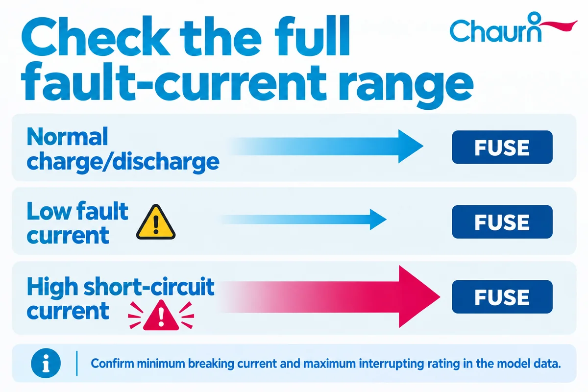
Estimate the current that could flow through each device for the relevant fault locations. Consider battery state of charge, temperature, the number of connected racks and the resistance of the fault path. The lowest credible fault current through the fuse can be as important as the highest. Then compare the resulting range with the selected fuse’s published operating class, time-current curve and breaking limits.
A full-range battery fuse and a partial-range fuse can serve different duties. The designation on one manufacturer’s datasheet cannot be assumed for another product or variant. Ask for documented performance covering the actual current range, including faults that develop without a large instantaneous short circuit.
Opening a fuse also depends on current passing through it. A fault confined inside a cell may not produce that current through an external rack fuse. Battery monitoring, thermal controls and contactors address other parts of the protection strategy.
Size for repeated charge and discharge duty
Normal ESS operation changes current direction and may hold high current for long periods. Use the site’s real duty profile: charge current, discharge current, overload duration, repetition, ambient temperature, cabinet ventilation and terminal temperature. A single steady-state number can miss the heating caused by cycling.
Compare the profile with the model’s temperature-rise and derating information. Connections matter. A fuse tested with one busbar size or cooling condition may run hotter in another assembly. Check the fuse, holder, terminals and adjacent cable as an installed system.
Bidirectional operation is a circuit condition to verify, not a feature to infer from a DC voltage marking. Ask for the relevant current-direction and interruption evidence for the chosen device. Also check maximum continuous DC voltage across the fuse under the system’s permitted operating states; a nominal bus label is an incomplete basis for selection.
Coordinate fuses with racks, contactors and the PCS
Coordination asks which device should open for each fault, and whether the others can withstand the energy until that happens. For a rack fault, compare rack-fuse and main-fuse time-current curves over the expected fault range. Then compare total clearing I²t and peak let-through with the withstand of cables, busbars and converter components. A calculated fault current alone does not answer the question.
Contactors provide routine switching within their ratings. A fuse interrupts current according to its characteristics. The article pyrofuse for energy storage system covers a distinct triggered device. A commanded pyrofuse may serve a separate isolation function where the design calls for it. Assign each device a role and document what happens if control power or communication is lost.
Walk through one fault at a time. A useful review records the fault location, which sources feed it, the intended operating device, the time to clear, and what stays energized. This exposes gaps that a list of individual component ratings can hide.
What to request before specifying an ESS fuse
Give the supplier enough information to evaluate a real part number. A drawing and fault study are more useful than an inquiry that says only “1500 V ESS fuse.”
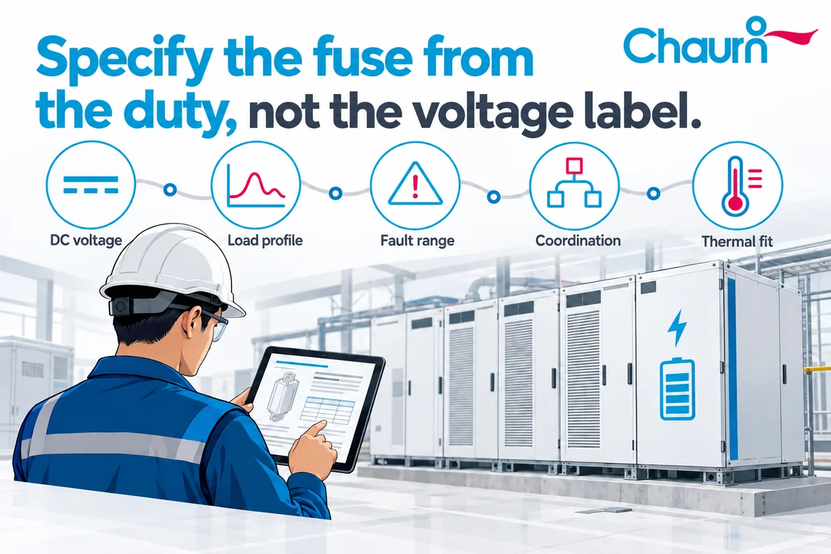
- The single-line diagram, installation point and required protection boundary.
- Maximum operating DC voltage and the charge, discharge and overload current profile.
- Minimum and maximum prospective fault current through the proposed fuse, with the circuit inductance or time constant.
- Required clearing performance and the withstand limits of cables, busbars, battery racks and PCS equipment.
- Ambient temperature, enclosure ventilation, holder or busbar design, mounting space and applicable project requirements.
IEC 60269-7:2021 sets supplementary requirements for fuse-links protecting batteries and battery systems in circuits up to 1,500 V DC. Ask whether the proposed model has the documentation required by your project; the standard’s scope does not establish that any particular Chauron model is certified to it.
Browse Chauron’s hvdc fuse category to identify candidates for ESS distribution, then compare the current datasheet and test conditions with the duty above. The product overview covers more than one application and voltage class, so confirm the exact variant before design-in.
ESS fuse questions
Is an ESS fuse the same as a battery rack fuse?
“ESS fuse” describes the application. A rack fuse is installed at a particular point in the storage system, usually to protect a rack connection or help isolate that rack from a shared fault. Other ESS fuses may sit at a string, combiner or PCS input. The electrical duty changes with the position.
Can I choose an ESS fuse from battery capacity in kWh?
No. Capacity describes stored energy, while fuse selection depends on DC voltage, normal current, fault current, circuit conditions and required clearing behavior. Two systems with the same kWh rating can have different numbers of racks and different current paths. Start with the electrical architecture and the actual duty profile.
What is minimum breaking current?
It is the lowest current at which the fuse’s stated breaking performance applies under the specified conditions. A fault below that value may require another protective function or a different fuse class. Read the applicable product datasheet carefully: maximum breaking capacity and minimum breaking current describe different ends of the fault range.
Does a 1500 V DC rating make a fuse suitable for every 1500 V ESS?
No. Check the maximum voltage that can appear across the device, its current duty, interruption range, circuit inductance, temperature and coordination with neighboring equipment. The voltage rating is one filter. Final approval depends on model-specific data and the assembled system’s requirements.
What happens if a rack fuse opens?
It interrupts the path through that fuse if the event falls within its specified operating conditions. Other racks and sections of the DC system may remain energized. The project should define how the control system detects the operation, prevents an unsafe restart and handles service. A blown fuse is evidence of a fault that needs diagnosis.
Should an ESS use a fuse, a contactor or a pyrofuse?
That depends on the functions required at each location. Contactors handle controlled switching within their limits; conventional fuses respond to overcurrent; a pyrofuse can provide a commanded single-use disconnection when the design calls for one. Evaluate them together against the fault cases rather than assuming one device covers every task.
Discuss an ESS fuse application with Chauron
Send the single-line diagram, voltage and current profile, fault range, installation details and required clearing results when requesting an ESS fuse recommendation from Chauron. Those inputs make it possible to compare a specific Chauron model with the protection duty and identify any test evidence still needed.