
An EV pyro fuse is a single-use, pyrotechnically operated disconnect that opens a selected battery power path after a valid trigger. In an electric vehicle, it can support emergency isolation after a crash or electrical fault. Its effectiveness depends on the complete system: detection, firing energy, interruption capability and the circuit it actually disconnects.
Before selecting a part, define the current path that must open, the conditions that require it, and how the vehicle will confirm disconnection. These requirements connect the component specification to the battery system it has to protect.
Where the EV pyro fuse sits in the power path
A traction-battery pyro fuse may be integrated into the battery disconnect unit (BDU), battery junction box or another high-voltage assembly. Its location defines the conductors and loads that can be separated from the battery. The vehicle architecture determines how many disconnects are needed and where they sit.
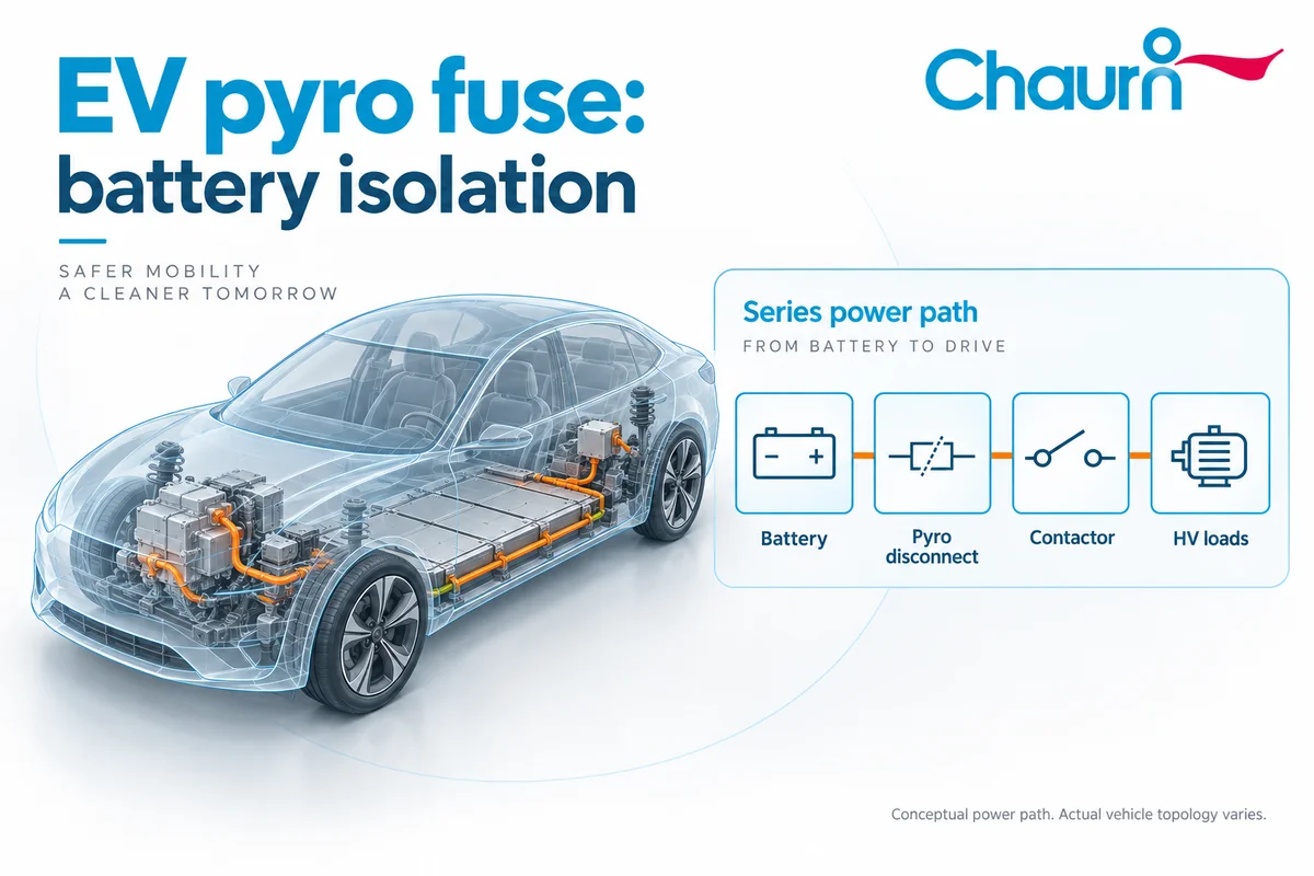
Start with the vehicle power diagram. Trace the battery connection to the traction inverter, charging circuit and auxiliary high-voltage loads. Then mark the exact boundary created when the pyro fuse opens. A branch connected on the battery side of that boundary may remain energized; a parallel path may defeat the intended separation.
Repeat the check during DC charging, precharge and service. Contactor positions and connected equipment can change which sources supply the circuit.
A conventional battery fuse responds to overcurrent according to its electrical characteristics. A commanded pyro disconnect can open the path following a control decision. For the device mechanism, see how a pyrofuse works. Assign each protection device a defined role in the battery circuit.
How an EV pyro fuse receives its firing command
In an actively triggered design, sensors and control logic identify the condition requiring disconnection. A driver supplies the specified electrical pulse to the initiator, which operates the disconnect mechanism. Crash information can be a trigger input even when current alone would not justify a trip.
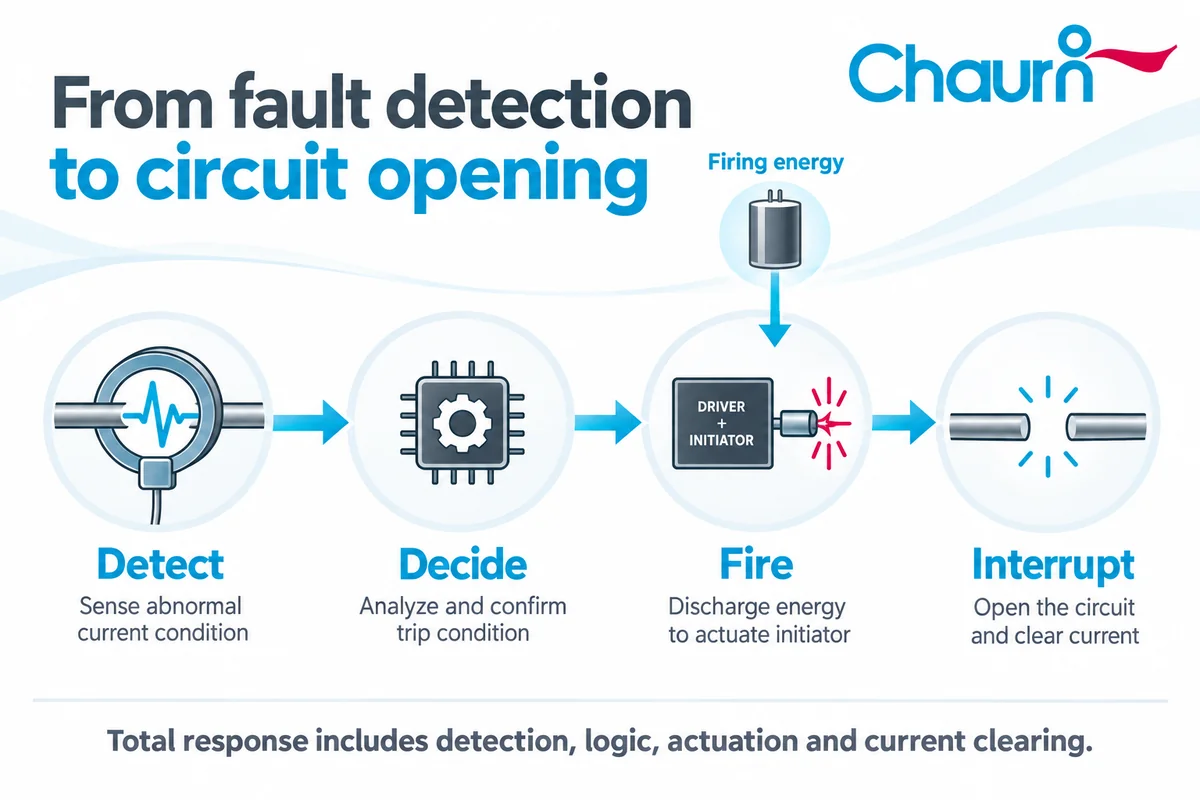
The initiator and its driver are different parts. The pyrofuse squib starts the mechanical action; the driver controls the electrical energy delivered to it. Neither component, by itself, establishes that the high-voltage circuit has been interrupted.
Check the proposed driver’s triggering options and diagnostics against the initiator requirements. Where the design uses an energy-reservoir capacitor, include its monitoring in the review. The available functions depend on the selected driver.
Check whether the device can fire if low-voltage power disappears just before the request. Any stored firing energy needs to remain available under the specified supply, temperature and fault conditions. Include a broken harness and loss of controller communication in the assessment.
Build a fault-response matrix before choosing a part
For each fault, record the required action and the evidence that confirms it worked. Use the following cases during the review; the vehicle manufacturer sets the deployment thresholds and timing.
| Operating condition | Design question | Evidence to request |
|---|---|---|
| Normal driving, regeneration and charging | Can the system carry its full duty profile without overheating or unintended deployment? | Thermal results for the installed assembly and trigger immunity checks. |
| Crash command with little load current | Can the selected path open when a large overcurrent is absent? | Validated commanded-disconnect behavior and a defined isolation boundary. |
| High-current short circuit | Which protection device clears the fault, and within what time? | Coordinated interruption results at representative voltage, current and inductance. |
| Contactor commanded open but still conducting | Does the alternative disconnect remove the hazardous path? | Failure-response analysis, including possible parallel supply paths. |
| Loss of the normal firing supply | Is deployment still required and, if so, how is it supported? | Evidence for the available firing-energy source and the intended degraded-state response. |
| Deployment completed | What remains energized, and how is reconnection prevented? | Post-event state handling, isolation checks and the approved service process. |
Assign an owner to each response. Battery controls, restraint controls and power-distribution teams may handle different stages, so the handoff between them needs an explicit owner too.
Coordinate the pyro fuse, contactor and passive fuse
The protection sequence should follow the fault scenario. Contactors provide repeatable switching within their specified limits. Passive fuses respond to overcurrent. A pyro fuse provides a one-time interruption function with a trigger mechanism determined by its design. Chauron’s fuse and pyrofuse comparison explains the component-level differences.
The opening sequence depends on the fault. A controlled contactor shutdown may suit one event, while a more urgent fault may leave no time to wait for an unsuccessful opening attempt. Define the sequence and permitted delay for each case.
The vehicle’s total response includes detection and decision delays, followed by initiator operation, mechanical separation and current clearing. Check which of these intervals the supplier includes in its quoted action time.
Place those intervals on one timeline and compare the total with the allowed fault duration. Record the start and end points of each measurement so that supplier figures can be compared on the same basis.
What an open pyro fuse does not make safe
Opening a battery connection does not remove the energy stored in the cells. Downstream capacitors can also retain charge. An interrupted current path is therefore only one part of the vehicle’s post-event electrical state.
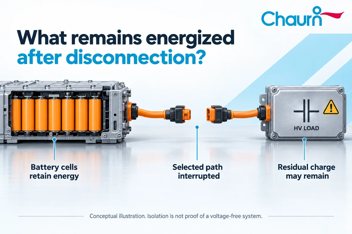
The review should identify battery-side conductors, residual charge and any other connected energy source. Define how the system verifies the required electrical state and what happens if verification fails. A software record that a firing command was sent is not, on its own, proof of physical separation.
Emergency disconnection also cannot guarantee that an internal cell reaction will stop. The battery’s thermal protection and the response to damaged cells need their own provisions. Avoid treating a successful external disconnect as evidence that a damaged pack is ready for handling.
Prepare an EV pyro fuse application brief
Send the supplier the electrical requirements together with the fault-response matrix. A 400V or 800V platform label leaves too much unspecified for model selection.
- A power-path diagram showing the disconnect location, branches and intended isolation boundary.
- Maximum battery voltage, continuous current, charging duty, current peaks and local thermal conditions.
- The fault-current range, representative circuit inductance and allowable response time.
- The proposed driver, available firing energy, harness conditions and diagnostic requirements.
- Packaging, terminal and mounting details, environmental requirements, and the tests needed for the installed assembly.
Use the brief to compare Chauron pyrofuse models for EV battery systems. Shortlist the models whose published conditions match the application, then ask for the current datasheet and the evidence needed to resolve any remaining differences in operating or fault conditions.
EV pyro fuse FAQ
Does every collision fire an EV pyro fuse?
No universal deployment rule applies to all vehicles. The manufacturer defines which crash signals and system conditions require an irreversible disconnect. A minor impact should not be assumed to deploy the device, and the absence of deployment does not establish that a damaged vehicle is safe.
Is the pyro fuse the same as the battery disconnect unit?
No. The BDU is an assembly that can contain switching, sensing and protection components. A pyro fuse is one possible component within that assembly. Its presence, position and function depend on the design, so the names should not be used interchangeably when specifying a part.
Can an EV pyro fuse be reset?
A deployed pyrotechnic disconnect is a single-use device. Restoring operation requires the approved replacement and inspection process, including investigation of the initiating event. Clearing a fault code does not restore the interrupted conductor or establish that the surrounding battery system is fit for use.
Does a squib fault mean the high-voltage path is already open?
Not necessarily. A diagnostic fault can concern the firing circuit or its monitoring function. The meaning depends on the vehicle and fault code. Diagnosis must distinguish a trigger-circuit problem, a deployment request and confirmed physical interruption; these are different states with different service consequences.
Can an EV pyro fuse replace the main passive fuse?
That requires a review of the complete protection architecture. Some devices combine functions, while others rely on an external trigger. The proposed arrangement must cover its required fault cases, including relevant control or supply failures. A fast deployment claim alone does not establish equivalent protection.
Is a matching voltage rating enough to select a replacement?
No. Interruption conditions, current-carrying capability, trigger characteristics, interfaces and vehicle approval also matter. For an existing vehicle, use the manufacturer’s specified service part and procedure. A component chosen for a new engineering project is not automatically a suitable replacement in a production vehicle.
Discuss your battery disconnect requirements
For a model recommendation, send your EV pyrofuse requirements to Chauron. Include the power-path diagram, electrical duty, trigger interface and fault-response matrix, along with any validation questions that still need an answer.