
A ground fault occurs when electrical current leaves its intended circuit path and flows into earth, a grounded conductor, an equipment enclosure or another conductive surface. It may result from damaged insulation, moisture, loose wiring, contamination or mechanical damage.
Ground faults can cause electric shock, overheating, equipment failure and fire. In electric vehicles, battery energy storage systems, photovoltaic installations and DC fast chargers, they may also indicate deteriorating insulation between a high-voltage circuit and the chassis or protective earth.
I. What Is a Ground Fault?
According to the NIST definition of a ground fault, it is current flowing outside the normal circuit path through a grounding conductor, conductive material or another ground-return path.
Under normal conditions, current flows from the source through the load and returns through the designated conductor. During a ground fault, part or all of that current follows an unintended path.
- A live conductor touches a grounded metal enclosure.
- Damaged cable insulation allows current to reach a chassis.
- Water creates a conductive path to earth.
- A DC bus develops reduced insulation resistance to ground.
- Battery wiring contacts the vehicle body after mechanical damage.
A ground fault does not always produce extremely high current. Its magnitude depends on system voltage, grounding topology, fault impedance, conductor resistance and the available return path. A high-resistance earth fault may therefore remain below the operating threshold of a conventional overcurrent fuse.
II. What Causes a Ground Fault?
Most ground faults begin with a loss of electrical insulation or an unintended connection between an energized conductor and a grounded conductive part.
- Aged or damaged insulation: Heat, electrical stress and long-term operation can weaken cable and component insulation.
- Moisture or coolant intrusion: Water, condensation and battery coolant can reduce insulation resistance.
- Loose or damaged wiring: Vibration, abrasion, incorrect routing and loose terminals may expose live conductors.
- Conductive contamination: Dust, metal particles, salt and chemical residue can bridge insulation surfaces.
- Mechanical impact: Collisions, crushed cables and damaged battery enclosures can connect high-voltage conductors to the chassis.
- Installation errors: Incorrect bonding, inadequate creepage distance or damaged terminals may create an unintended ground path.
III. Ground Fault vs. Short Circuit vs. Arc Fault
| Fault type | Current path | Typical characteristic | Main hazard |
|---|---|---|---|
| Ground fault | Live conductor to earth, chassis or grounded enclosure | Current may be high or limited by fault impedance | Shock, fire and energized metalwork |
| Short circuit | Between conductors at different potentials | Usually a low-impedance, high-current path | Thermal and mechanical damage |
| Arc fault | Through an electrical arc across a gap | Intermittent or sustained arcing | Extreme heat and ignition |
| Overload | Through the normal circuit path | Current exceeds the circuit’s continuous rating | Conductor and component overheating |
A low-impedance ground fault can behave like a short circuit and generate sufficient current to operate a fuse or circuit breaker. A high-resistance ground fault may produce only leakage current, requiring a ground-fault relay, residual-current device or insulation monitoring device.
IV. Why Are Ground Faults Dangerous?
Electric shock
A conductive enclosure or vehicle chassis may rise to a dangerous potential if fault current is not safely controlled. A person touching the energized surface may become part of the current path.
Fire and overheating
Fault current passing through a resistive connection can generate localized heat. Damaged insulation, terminals and surrounding materials may ignite before a conventional overcurrent device operates.
Equipment damage and downtime
Ground faults can damage battery modules, inverters, power conversion systems, charging modules, contactors and control electronics. In data centers and industrial DC networks, an unexpected shutdown may also interrupt critical loads.
Escalation to a second fault
Some isolated or ungrounded DC systems can continue operating after the first insulation fault. A second fault on the opposite pole may create a severe pole-to-pole current path through the chassis or grounding network.
V. How Is a Ground Fault Detected?
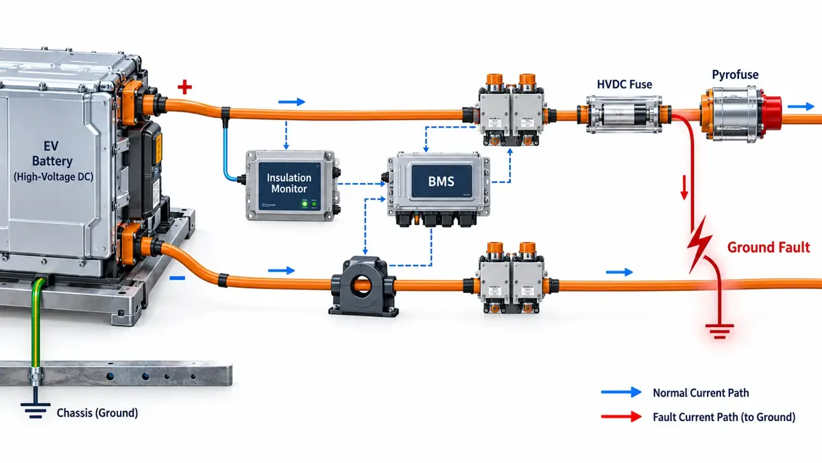
Residual-current measurement
A current transformer or electronic sensor compares outgoing and returning current. An imbalance indicates that current is escaping through another path.
Insulation monitoring
An insulation monitoring device (IMD) measures insulation resistance between energized conductors and protective earth or chassis. Texas Instruments identifies battery management systems, energy storage equipment, solar inverters and DC charging equipment as common high-voltage insulation-monitoring applications.
Ground-fault relays
Industrial systems may use relays that monitor zero-sequence current, residual current or voltage displacement. When the measured value exceeds a defined threshold, the relay issues an alarm or trip command.
BMS and vehicle isolation monitoring
In an EV, the battery management system supervises isolation resistance between the high-voltage battery and vehicle chassis. If isolation falls below the permitted threshold, the control system may open contactors, restrict charging or trigger an emergency disconnection device.
VI. How Is a Ground Fault Cleared?
Detection and interruption are separate functions. A sensor identifies the abnormal condition; another device must isolate the affected circuit.
- A GFCI, RCD or residual-current circuit breaker
- A circuit breaker operated by a ground-fault relay
- Battery contactors
- A conventional fuse during a sufficiently high overcurrent
- An actively triggered Pyrofuse
- A coordinated combination of monitoring, contactors and backup fuses
A fuse responds to current and cannot independently measure insulation resistance. Consequently, low-level leakage may not operate an overcurrent fuse. Where a BMS or safety controller must command rapid physical isolation, it is important to understand what a Pyrofuse is and how it complements contactors and conventional fuses.
VII. Ground Faults in Electric Vehicles
An EV high-voltage system is generally isolated from the conductive vehicle chassis. The battery, inverter, motor, on-board charger, electric compressor and DC cabling must maintain adequate isolation.
- Damaged orange high-voltage cables
- Coolant leakage inside the battery pack
- Inverter or motor insulation failure
- Contaminated connectors
- Collision damage
- Water entering a high-voltage enclosure
The isolation monitoring system can detect declining resistance before the condition becomes a direct short circuit. Depending on severity, the BMS may open the main contactors or activate a Pyrofuse in an electric vehicle. Engineers should also compare active Pyrofuse triggering with passive overcurrent operation when developing the complete safety concept.
VIII. Ground Faults in Energy Storage and Charging Systems
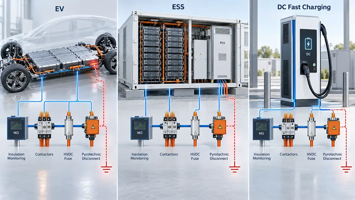
Battery energy storage systems contain long DC strings, power conversion equipment, busbars and numerous connection points. Moisture, wiring damage or insulation degradation may create a positive-to-ground or negative-to-ground fault.
In an isolated DC architecture, the first fault can shift pole-to-ground voltages without immediately producing a large overcurrent. Continuous insulation monitoring is therefore important. A second fault can create a much more destructive current path.
Protection should coordinate string and rack fuses, insulation monitoring, ground-fault detection, contactors or DC breakers, PCS protection and system-level emergency shutdown controls. DC fast chargers face similar risks because they combine high voltage, outdoor exposure, power electronics and vehicle connections.
IX. How to Locate a Ground Fault Safely
Ground-fault troubleshooting should be performed only by qualified personnel using procedures appropriate for the voltage and equipment.
- De-energize and secure the system according to the applicable safety procedure.
- Review alarms and event logs from the BMS, IMD, inverter or protection relay.
- Divide the system into sections to narrow down the affected circuit.
- Inspect cables, connectors and enclosures for moisture, abrasion, contamination and impact damage.
- Measure insulation resistance using equipment and test voltages approved for the system.
- Disconnect sensitive electronics before insulation testing when required by the manufacturer.
- Repair the underlying cause, not merely reset the alarm.
- Repeat insulation and functional tests before returning the equipment to service.
Do not use a basic continuity test as the only assessment of a high-voltage insulation fault. Intermittent faults may appear only under humidity, vibration, temperature or operating voltage.
X. How to Design Effective Ground-Fault Protection
A reliable protection design starts with the grounding method and expected fault-current range. Engineers should evaluate:
- Maximum operating and transient voltage
- Solidly grounded, resistance-grounded or isolated topology
- Minimum and maximum ground-fault current
- Insulation-resistance thresholds
- Touch-voltage and personnel-safety requirements
- System capacitance to ground
- Required detection and interruption time
- Contactor DC breaking capability
- Fuse voltage rating and breaking capacity
- Fault-current time constant
- Coordination with BMS, PCS and inverter controls
- Single-fault and second-fault behavior
No single component covers every ground-fault condition. Strong designs use layered protection: insulation monitoring for early detection, control logic for decision-making, contactors or triggered devices for commanded isolation and HVDC fuses for high-current backup protection.
XI. Frequently Asked Questions
Is a ground fault the same as an earth fault?
The terms are often used interchangeably. Both generally describe unintended current flow from an energized conductor to earth, protective ground, chassis or grounded conductive material.
Will a normal fuse clear a ground fault?
Only when the fault current enters the fuse’s operating range and persists long enough. A high-resistance ground fault may remain below that range and require dedicated detection. See the difference between a fuse and a Pyrofuse when selecting passive and active isolation devices.
Can a ground fault occur in a DC system?
Yes. DC ground faults occur in EV batteries, photovoltaic arrays, energy storage systems, UPS equipment, data centers and DC charging infrastructure.
What is a pole-to-ground fault?
It is an unintended connection between the positive or negative pole of a DC system and ground or chassis. Its behavior depends heavily on the system grounding topology.
What is the difference between a ground-fault detector and a fuse?
A detector senses leakage, residual current or reduced insulation resistance. A fuse interrupts current when its time-current operating conditions are reached.
Can an EV continue operating after an insulation fault?
The response depends on system design, fault severity and applicable safety requirements. The vehicle may issue a warning, restrict operation, open contactors or initiate emergency isolation.
XII. Conclusion
A ground fault is an unintended current path between an energized circuit and earth, chassis or grounded conductive material. It may begin as small leakage current and later develop into a destructive short circuit.
Effective protection requires coordinated insulation monitoring, ground-fault detection, control logic, contactors, HVDC fuses and actively triggered disconnect devices. For an EV, energy storage, charging or industrial DC project, Chauron can review the system voltage, continuous current, prospective fault current, time constant and isolation strategy.
Contact Chauron for HVDC fuse and Pyrofuse selection support.